Ansys Mechanical Day 1, Intro
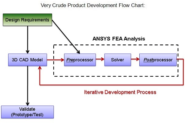
Overview: FEA workflow:
+ FEA (in general): + Ansys Mechanical:
– Pre-processor – Assign Material, Loads/Supports, Mesh
– Solver – Solve the analysis
– Post processor – Review the Solution

To Start: Create the 6" H x 24" Wide x 120" Long Cantilever Beam geometry shown in the image to the left and import it into the Ansys Workbench.
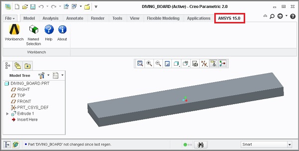
Note: There are two ways to import into Workbench
- Launch Workbench from within the CAD software (for example, Creo 2.0 is shown here).
- Launch Workbench “standalone”, and import the CAD data.
Walk through both methods.
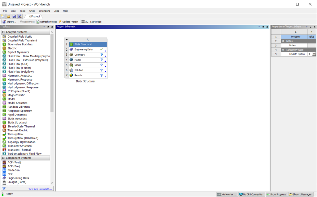
Familiarize Yourself: Ansys Workbench is a Multiphysics simulation tool. Take a tour of the interface.
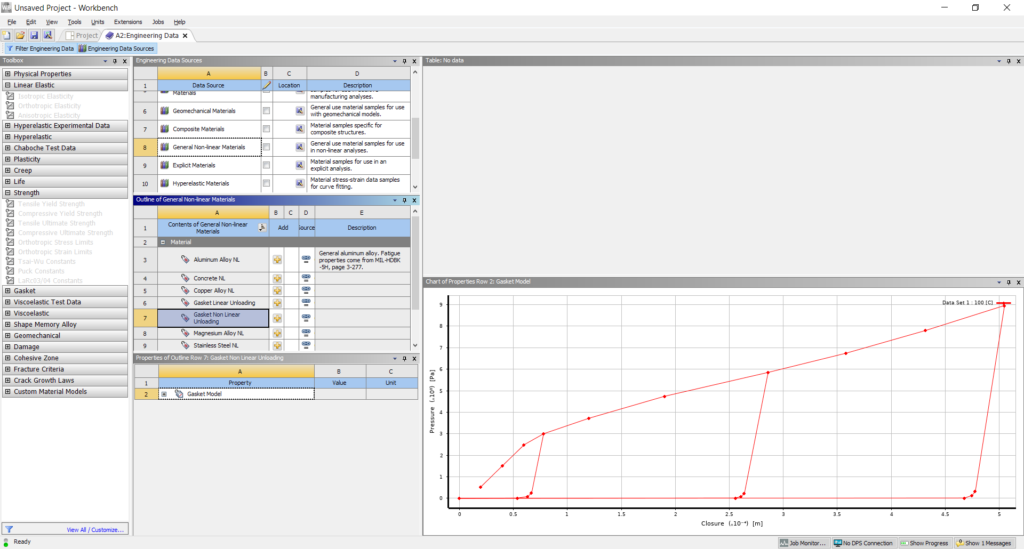
Prepare: Before launching Ansys Mechanical, add AL 6061 to the Engineering Database.
What is Granta?
What is an example of a nonlinear material?
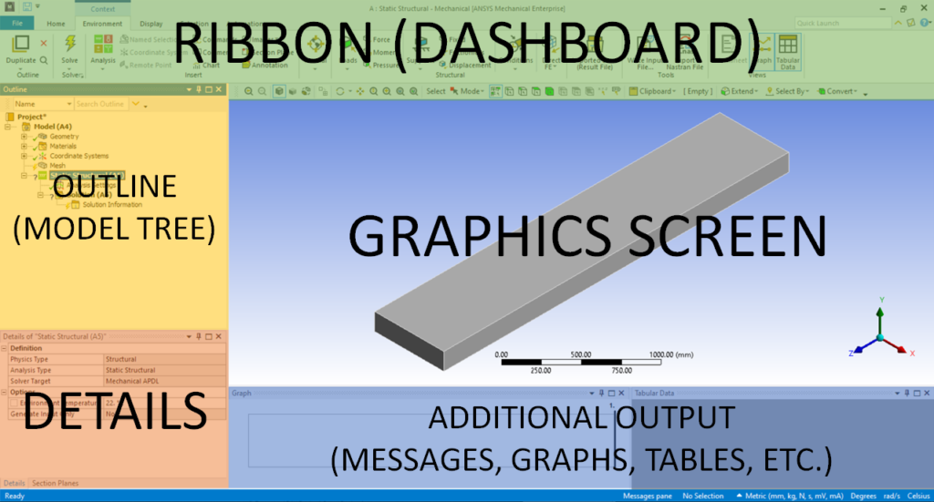
Launch: Open up Ansys Mechanical, and tour the CAD-like Interface
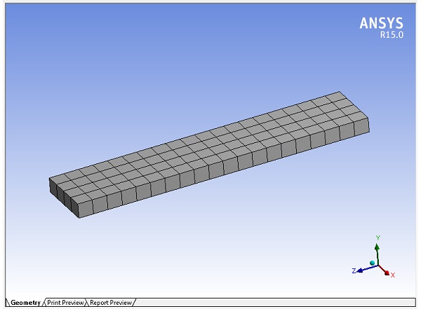
Next: Assign Material, and generate the Mesh
Discuss:
- The Geometry vs. The Mesh
- Hexahedra (aka “Hex” or “Brick”) vs. Tetrahedra (aka “Tet”)
- What are Element Midside Nodes, and how can they be utilized?
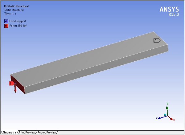
Next: Setup the analysis.
- Fixed Support at the far end of the board
- Force: 250 lbs in the -‘Y’ direction near the end of the board
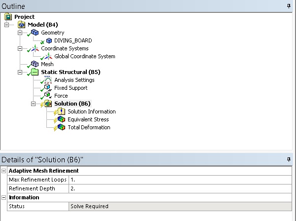
Next: Set up the rest of the analysis so it matches the image to the left.
Note: Pay attention to the status symbols in the outline window. What’s the difference between the Check mark and the Lightning Bolt?
Discuss: The relationship between the Ansys Workbench Environment and the underlying Code (APDL).
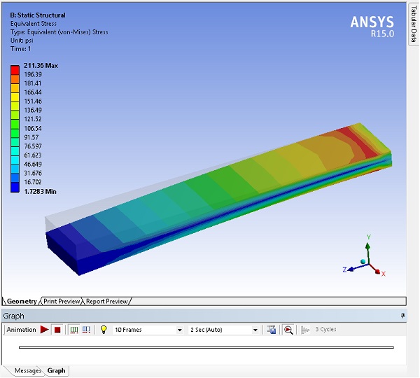
Next: Solve the Analysis, and review the results.
Note: The stress contour through the thickness of the part. Discuss the influence of the mesh.
Try:
- Customizing the Graphics screen (Legend, Display, etc.)
- Playing with the post-processing tools: Images, Animations, and Probes
- Add another 250 lbs load in the -‘X’ direction and rerun the analysis. Add a mesh control to smooth out the stress plot
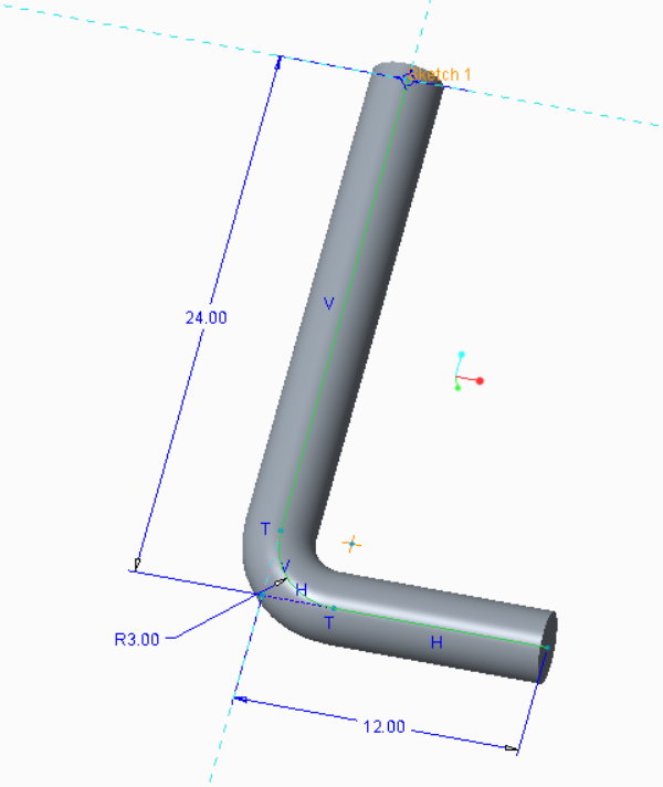
Next: Setup and solve a static structural analysis on the part in the image to the left using the same conditions as the above diving board model.
Note:
- The material is polyethylene
- The diameter of the cross-section is 3.00
- Refine the mesh so the stress contour is smooth
Try:
- Compare to the yield strength of polyethylene
- Change the 12″ long leg to 36″ and rerun the analysis. What’s different about the stress plot? What does this tell you about the possible failure mode?
- Increase the load 10X, and observe the new results. Were the results predictable? Is this good or bad?
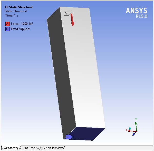
Next:
- Build a stainless steel column that is 5″ by 5″ by 20″.
- Constrain the bottom, and apply a 1,000 lbs compression load on the top.
- After refining the mesh and verifying convergence, review the stress plot, and determine what happened
Try: Constrain the bottom utilizing edges or even vertices, to reduce the stress concentrations.
Discuss: What are weak springs?
Challenge: Change the direction of the load (to tension), and repeat the exercise.
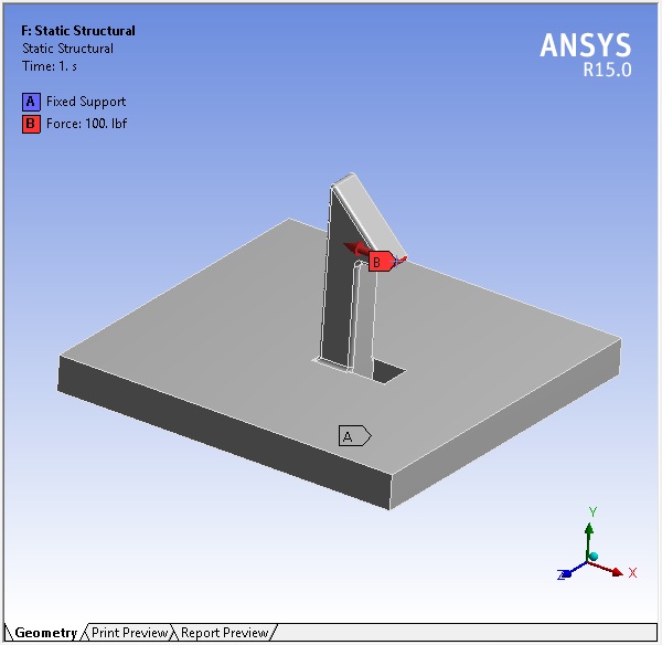
Next: Execute a static analysis on the linked model below. Fix the bottom, and push the clip inwards with a 100 lbs force.
Try:
- Conduct the analysis both with and without the radii on the model. What impact does this have on the mesh count?
- Utilize a mesh controls (such as Sphere of Influence) to ensure mesh independence.
- Instead of a force, push the clip in by 0.1″.
Model: Ansys Clip Model
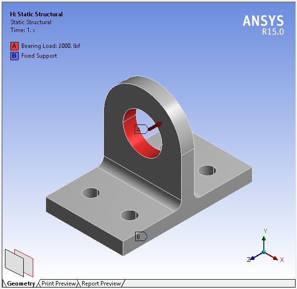
Next: Download the 6061 Aluminum lug model below, and pre-process; fix the bottom surface, and put a 2,000 lbf force at a 45 degree angle as shown in the image. Verify convergence and review the stress.
Try:
- Change the load to a bearing load and constrain the bolt hole surfaces instead as it is more realistic. Compare the stress plots before and after
- Brainstorm other methods of realistically constraining the bolt holes.
- Cut the model in half and rerun the analysis with a symmetry constraint. Are the results identical?
Model: Ansys Lug Model
© Fastway Engineering. All Rights Reserved. May not be duplicated without express written consent.

