Solidworks: A CAD/CAE Overview
While other companies in the CAD software industry often segment their products into distinct programs based on industry/feature set, Solidworks crams almost all of their supported features within one interface. This means that all parts of a product’s development process from design, simulation, and preparation for manufacturing can all be done within a single 3D CAD environment.
Design
3D Mechanical CAD
The main allure of programs like Solidworks is to allow users to create, edit, and most importantly visualize 3D products. Solidworks uses this 3D CAD environment as the portal to all other facets of its feature-set.
Main features provided by the environment include access to tools that make creating, modifying, and attaching parts an easy, drag-and-drop process. Since Solidworks is meant for manufacturable products, 3D models can easily be translated to 2D drawings, which can then be annotated and dimensioned for both designer and manufacturer use.
Also included are tools and pre-built models for commonly used design features, such as supports and vents. Models can also be shared throughout a company, meaning all designers have access to the same, already built designs that often define the company’s products.
Electrical Design
PCB
As Solidworks’ primary electrical design toolset, Solidworks PCB provides the groundwork for designing Printed Circuit Boards (PCBs) quickly and easily. Solidworks PCB maintains a level of interconnectivity with a product’s 3D model, meaning that changes made to a 2-D PCB design will instantly update the 3-D existing model. From there, the physical constraints of the PCB within the product can be analyzed and modified. This level of collaboration between the electrical and mechanical aspects of design is essential in reducing the number of failed prototypes and maximizing space within a product.
Electrical 3D
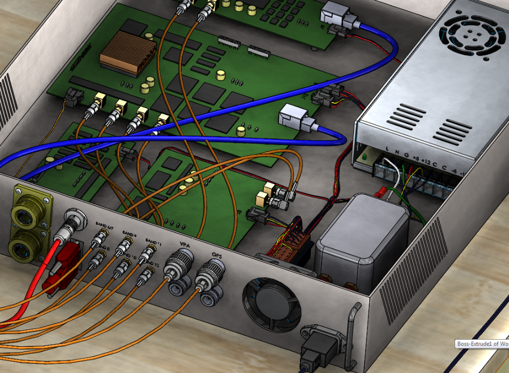
Building upon collaborative aspects of Solidworks PCB, Solidworks Electrical 3D allows wires and cables to be routed easily within a 3D model. Routing can be done manually or automatically, with changes done to either the electrical or mechanical aspects of the design being instantly synced with each other. In this way, multiple electrical and mechanical engineers can work on the same project, with all changes being accurately and quickly distributed to all users.

Solidworks’ Electrical Design features allows for the routing of cables and 3D representations of PCBs within a design. Source
Simulation
Motion
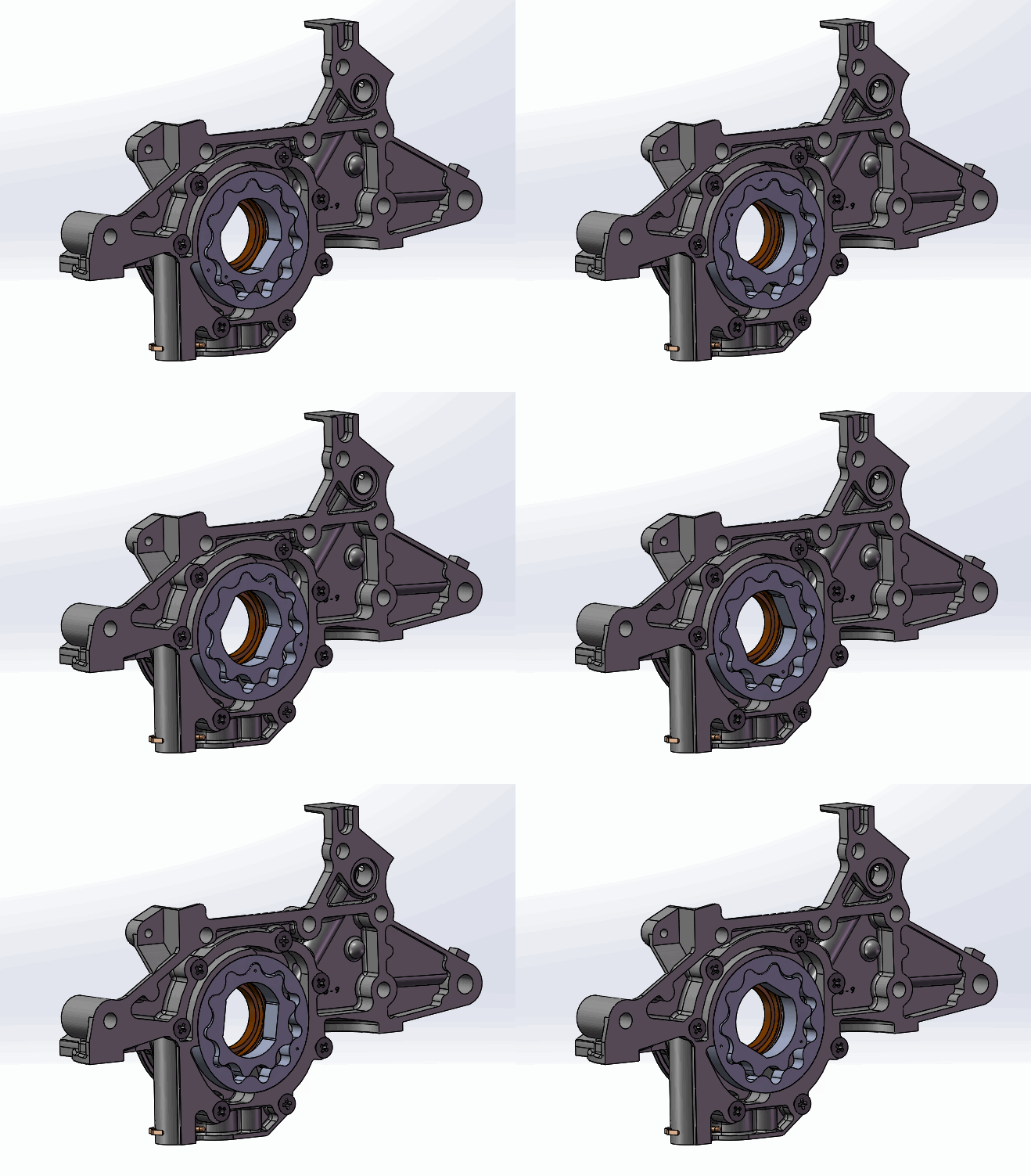
Solidworks’ support for motion simulation can be used for rigid body kinematics that can help calculate velocities, accelerations, and physical movements of an assembly. The motion tool is often used in conjunction with FEA analysis, since loads calculated by the Motion simulation can be easily carried into an FEA simulation.

Positive Displacement Oil Pump Mechanism in Solidworks Motion
Finite Element Analysis (FEA)
As the main part of Solidworks’ simulation toolset, its finite element analysis (FEA) capabilities allow users to simulate the effects of many types of real-world behavior. Supporting linear and non-linear static/dynamic analysis, Solidwork can help reduce the cost and tedious physical prototyping, dramatically reducing development time.
Simple (Linear)
The linear FEA capabilities found within Solidworks are meant to help quickly provide key insight into a part’s structural characteristics. This is done by using simplified representations of often complex interactions to gain a general sense of the part’s performance. Examples of linear FEA analysis results include stress, strain, displacements, and Factors of Safety (FOS).
Advanced (Non-Linear & Dynamic)
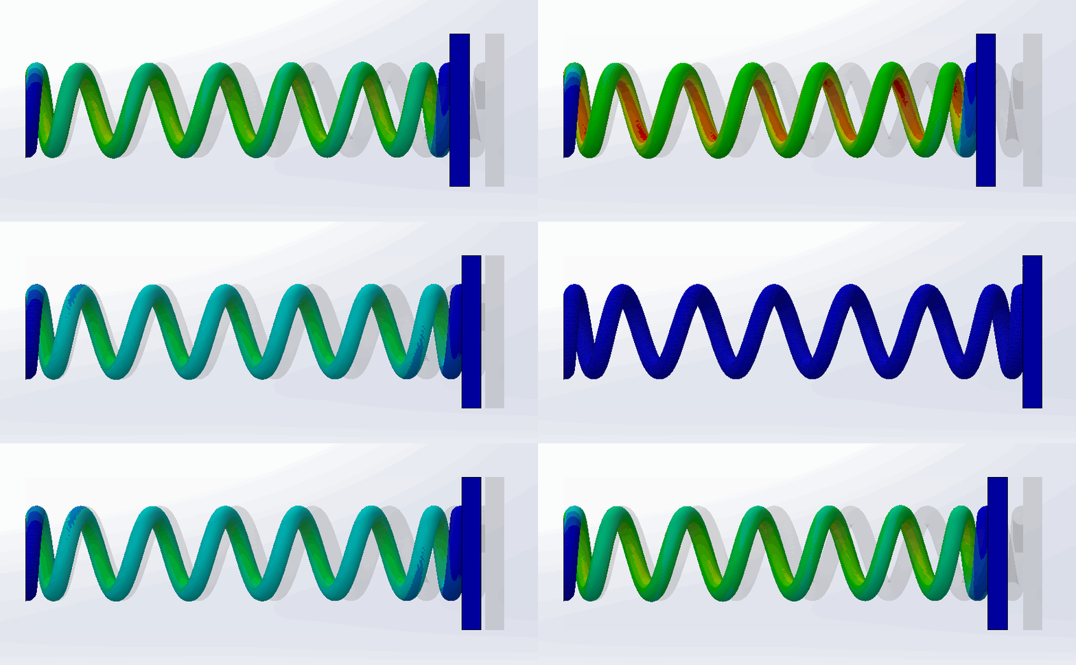
While linear FEA simulations are excellent for steady state, stiff bodies, any sort of excessive deformation or environmental changes will lead to incorrect results. To remedy this, Solidworks Simulation also provides support for non linear dynamic interactions, which can help fine-tune an existing linear result or might even be required for an accurate representation of a part’s operating environment.

Solidworks Nonlinear Stress Analysis with Large Deflection and Friction ( 150k elements, 5.5 hrs. with Intel Direct Sparse Solver)
Flow
While Solidworks’ FEA features are meant for analyzing the impact of external forces on a solid product during its use, Flow Simulation is meant to predict the flow of fluids through or around a product. This of course has a wide range of uses, from verifying the design of an HVAC system to optimizing the design of a release valve to maximize water flow rate.
Achieved through the Finite Volume Method (FVM), Solidworks’ Flow Simulation reduces the partial differential equations governing the flow of a fluid into algebraic expressions. This application of Computational Fluid Dynamics (CFD) allows Solidworks to give a detailed visual representation of the fluid flow, which is not often possible with a physical test.
Design for Manufacturing
Sheetmetal
As another testament to Solidworks’ role as a platform for creating manufacturable products, it only seems natural that it would include specific features tailored towards one of the most commonly used materials – sheetmetal. While designing for sheetmetal could be done using typical modelling techniques, sheetmetals main use-case as a cheap, easy to work with material motivated a more custom-made solution.
With Solidworks’ Sheetmetal design capabilities, a base sheetmetal model can be shaped into the desired part in a way that’s very similar to how its physical counterpart would be created. This means that not only will a sheetmetal design be easy to create in Solidworks, it will be easily manufacturable.
Plastics
During injection molding, molten plastic is injected into a mold, creating the part in an easily mass producible manner. However, this process requires tight control over many manufacturing variables, such as how the plastic melts and how it cools. This makes simulation a valuable part of designing for this type of manufacturing.
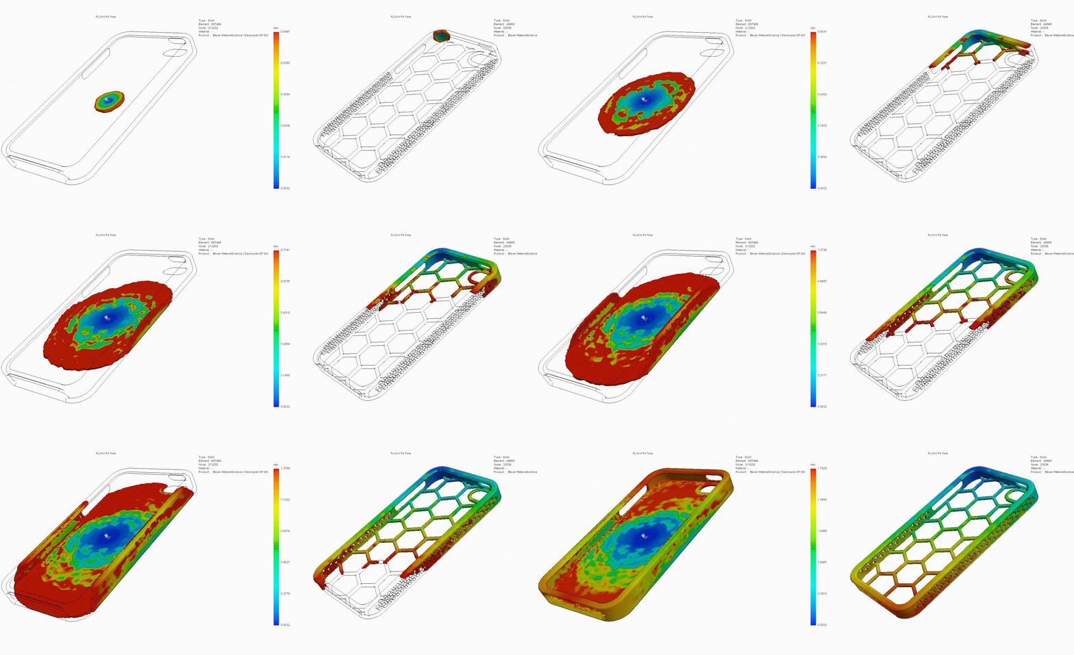
In a similar vein as Solidworks’ sheetmetal capabilities, Solidworks’ Plastics combines elements of flow and thermal simulation to aid in the design of injection molded plastic parts and their molds. This is done by analyzing how a part’s mold will affect the flow of the molten plastic, highlighting areas of potential issues and optimizing the model to prevent them.

The injection molding process for two different phone case designs is simulated with Solidworks. Source
Technical Communication
Because of Solidworks’ widespread use in industry, it only makes sense that it has a tool made for easily creating and managing technical communications. Using Solidworks Composer, the graphical content produced can be crafted for a variety of use cases, from simply, flashy promotional content to detailed, insightful assembly instructions. While the use of existing 3D models dramatically simplifies the creation of content, the connection to actual CAD data means that any changes in said data can be easily migrated to created content. Static renderings and animations can be easily recreated using the updated model, saving countless hours of work.
Product Data Management (PDM)
A necessary part of any modern product development process is the organization of product data. Part datasheets, bill of materials, schematics, CAD files, simulation results, and countless other types of documentation are created for every single iteration of a design. Early design changes need to be documented for future reference, while revisions made near the manufacturing stage must go through an often tedious Engineering Change Order (ECO), where the often cascading effects of a change are tabulated for review.
Solidworks provides solutions for all these problems and more, from tools to keep track of design revisions and documentation, to management software with the ability to observe company productivity either as a whole or on a department level.
Getting to Know Solidworks
Solidworks is inherently an easy-to-learn and intuitive software that’s coupled with a wide variety of videos and web-based tutorials, meaning the learning curve has never been smoother. However, in many cases designers don’t have the time (or patience!) for self-paced learning. Here at Fastway Engineering, we offer instructor-led classes for the not-so-intuitive capabilities of Solidworks, like their simulation tools. With classes like Introduction to FEA and Introduction to Mechanism Motion, our innovative project-based learning classes will pick up where your self-paced learning has left off.
References
Solidworks
- 3D CAD
- Electrical Design
- Simulation
- Simulation Overview
- Flow (CFD)
- Design for Manufacturing
- Technical Communication
- Product Data Management

