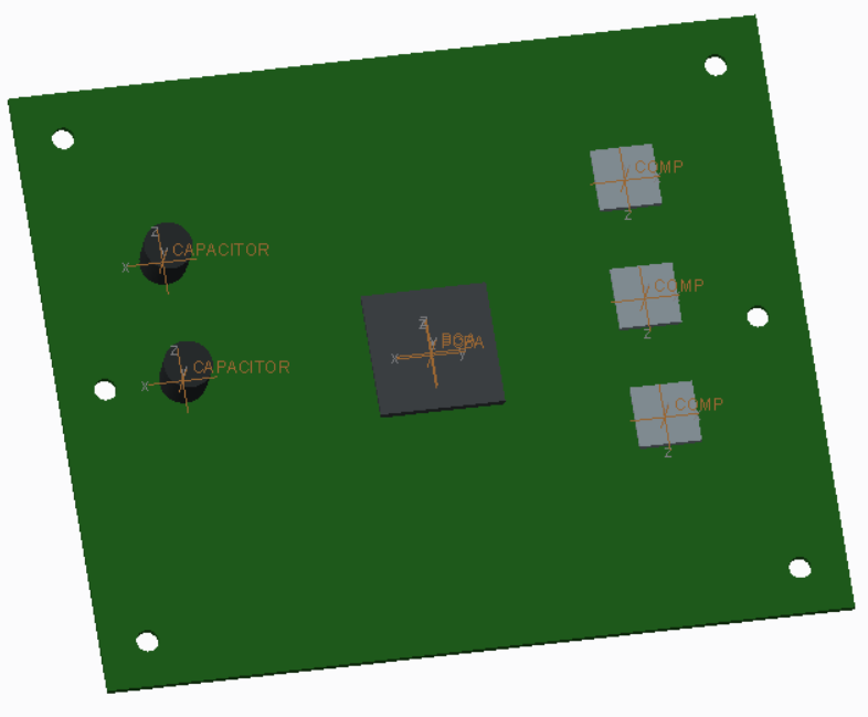
Overview: Download the linked printed circuit board assembly model below and use the supplied ‘pcba_input.xlsx’ file to establish material propeties and thermal loads.
Discuss: New types of thermal loads and constraints.
Next: Set the mounting hole surfaces to t=0, and execute the analysis.
Note: Pay attention to the speed of convergence. How many equations are being solved? How does this compare to the structural analysis?
Try:
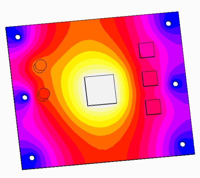
Utilize the handful of result viewing options for this thermal analysis
Change the boundary condition from t=0 to t=10. How does this change the temperature profile? Is this surprising?
Change the default interface for the FEA model and observe the impact on it
Next:
Update the ‘component’ heat load so that it is dependent on time
Use a table to force the components to ‘turn on’ after 60 seconds. Verify the function by reviewing the function and graphing it
Try: Use t=0 as the initial condition, and use automatic intervals.
Note:
How long does it take for the PCBA to reach a steady state?
What’s the hottest temperature on the capacitors?
What temperature is the middle component at t=2 mins?
Challenge: Update the component loads so they all turn off after 60 seconds. Using the steady state analysis, determine how long it takes for the PCBA to cool down.