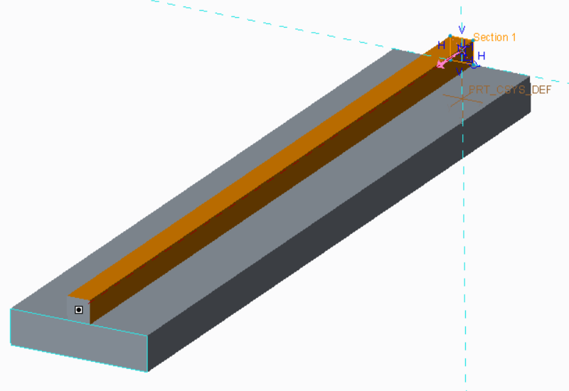
Overview: Rebuild (or Reuse) the cantilever beam created from the previous Modal Analysis Project, to fix the far face, and run a modal analysis.
Note: Only the first mode needs to be calculated for this exercise.
Pro Tip: Rename the dimensions of the rib so they will be easy to reference later (edit the properties of the dimension).
Next: Using the image to the left as a guide, create a new optimization design study that investigates the height of the rib and the thickness of the Cantilever Beam.
Note: These settings suggest:
The mass of the part is minimized while maintaining at least 10 Hz for the first mode
The design is optimized by changing the rib height and board thickness
Explore:
Run the analysis, and display the study status. Make an educated guess as to what the solution will look like
When complete, review the first mode frequency
Step through the optimization history and accept the optimized geometry. Go back into Creo Parametric and review the new values for rib height and board thickness. Is it close to what you predicted?
Use this method to optimize the sheet metal bracket from the ‘modal analysis tutor’. Remember the goal: reduce weight by 50% and maximize the first mode frequency
Discuss: What exactly is Creo doing when it is executing an Optimization Design Study.
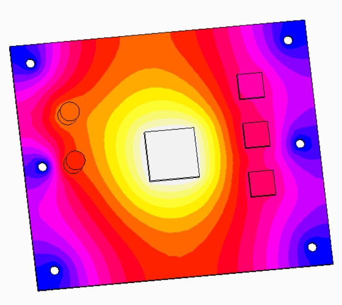
Next: Download the linked ‘PCBA’ model below or reuse a the previous one) and make the following changes:
Optimize the location of the components, BGA, and capacitors on the model to minimize its maximum temperature
Ensure the BGA is at least 1″ away from the edges of the board
Ensure nothing is within 0.5″ of each mounting hole
Pro Tip: Before completely automating the optimization consider performing a sensitivity analysis.